|
|
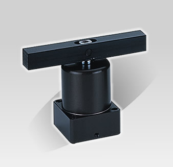
Hydraulic Swing Clamp Cylinder
- Can be used in MC clamp and specialized part-making machines. It is anexcellent means of raising production efficiency.
- After the piston's downstroke causes the cylinder to rotate to the design angle, it will continue downward in a straigth line until the swing clamp tightly grips the workpiece.
- To avoid excessive speed, is suggested that a flowcontrol value be installed when using the hydraulic swing clamp cylinder. To avoid damage to the cylinder bore and internal components, please do not clamp the workpiece during the swing stroke.
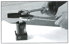
- If it is necessary to increase the length of the swing clamp, please do not exceed 1.5 time s the original length.
- The cylinder bore is made of carbon steed. The inner wall has been given a special treatment and polished for long operating life.
|
|
Specifications
| Bore Size (mm) |
Ø25 |
Ø32 |
Ø40 |
Ø50 |
Ø63 |
| Swing Stroke (mm) |
11 |
13 |
15 |
| Clamp Stroke (mm) |
11 |
13 |
15 |
| Using Media |
Hydraulic Oil |
| Max. Operating Pressure |
100kg/cm
² |
| Working Pressure |
5-70kg/cm² |
| Swing Direction |
Right or Left |
| Swing Degrees |
Standard 90°
(May be made on request) |
| Operation |
Double Acting |
|
|
Swing Clamp Locking Control Method

|
|
Clamping Force
| Bore Size (mm) |
Rod Size (mm) |
Pressure Area (cm²) |
Working Pressure kg/ cm² |
| 10 |
20 |
30 |
40 |
50 |
60 |
70 |
| Ø25 |
Ø18 |
2.37 |
24 |
47 |
71 |
95 |
119 |
142 |
166 |
| Ø32 |
Ø20 |
4.9 |
49 |
98 |
147 |
196 |
245 |
294 |
343 |
| Ø40 |
Ø22.4 |
8.63 |
86 |
173 |
259 |
345 |
432 |
518 |
604 |
| Ø50 |
Ø28 |
13.47 |
135 |
269 |
404 |
539 |
674 |
808 |
943 |
| Ø63 |
Ø35 |
21.55 |
216 |
431 |
647 |
862 |
1078 |
1293 |
1509 |
|
|
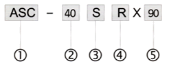
How To Place Order

 |
HPS Series |
 |
Bore Size Ø25, Ø32, Ø40, Ø50, Ø63 |
 |
S:Single Side Swing Clamp, D:Double Sides Swing Clamp |
 |
Swing Direction R or L |
 |
Swing Degrees 90° |
|


