|
|
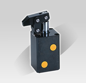
Hydraulic Lever - Type Cylinder
- The clamp of this type of hydraulic cylinder operates on a lever principle. The clamp is actuated when the piston is pushed out. Clamping force is greater than that generated by a swing clamp cylinder. Chief mechanical parts are installed on the exterior of the cylinder body for convenient maintenance.
- To insure durability and a long service life, the cylinder bore and clamp mechanism both employ structural carbon steel.
|
|
Residua gap when up
|
|
Dimensional Tab
Unit:mm
 |
MHLC-32N1 |
HLC-40 |
hlc-50 |
| Bore Size (mm) |
Ø32 |
Ø40 |
Ø50 |
| Rod Size(mm) |
Ø20 |
Ø22.4 |
Ø28 |
| Storke(mm) |
25 |
30 |
35 |
| Max. Operating Pressure |
100kg/cm² |
| Working Pressure |
5-70kg/cm² |
| Clamping Force 35kg/cm² |
220kg |
330kg |
530kg |
| A1 |
112 |
122 |
137 |
| A2 |
131 |
144.2 |
162.4 |
| B |
85 |
90 |
100 |
| C1 |
19 |
22.2 |
25.4 |
| C2 |
11 |
13 |
15 |
| C3 |
9 |
10 |
11 |
| D |
Ø8 |
Ø10 |
Ø12 |
| E1 |
25 |
30 |
35 |
| E2 |
5 |
5.5 |
6.5 |
| F |
64.5 |
77 |
89 |
| G1 |
55 |
66 |
76.5 |
| G2 |
22 |
26 |
30 |
| G3 |
24 |
29 |
33 |
| H |
3 |
4 |
5 |
| I1 |
Ø6.8 |
Ø9 |
Ø9 |
| I2 |
Ø11 |
Ø14 |
Ø14 |
| I3 |
7 |
9 |
9 |
| J |
57 |
69 |
75 |
| K |
44 |
52 |
58 |
| L1 |
19 |
19 |
21.5 |
| L2 |
38 |
40 |
45 |
| M |
1/8 PT |
1/4 PT |
1/4 PT |
| N1 |
22 |
26 |
30 |
| N2 |
22 |
26 |
32 |
| O-Ring |
P7 |
P8 |
P8 |
|
|
How To Place Order
 |
HPS Series |
 |
Blank: Strandard Line Type, M:Manifold Type |
 |
Borg Size Ø32, Ø40, Ø50 |
|
|
|

